The scientific instrument ripped apart to become a clock, the story of a long-neglected project seemingly making a comeback. Back in 2012 I came across this old voltmeter, with a strange display that I had better ideas for.
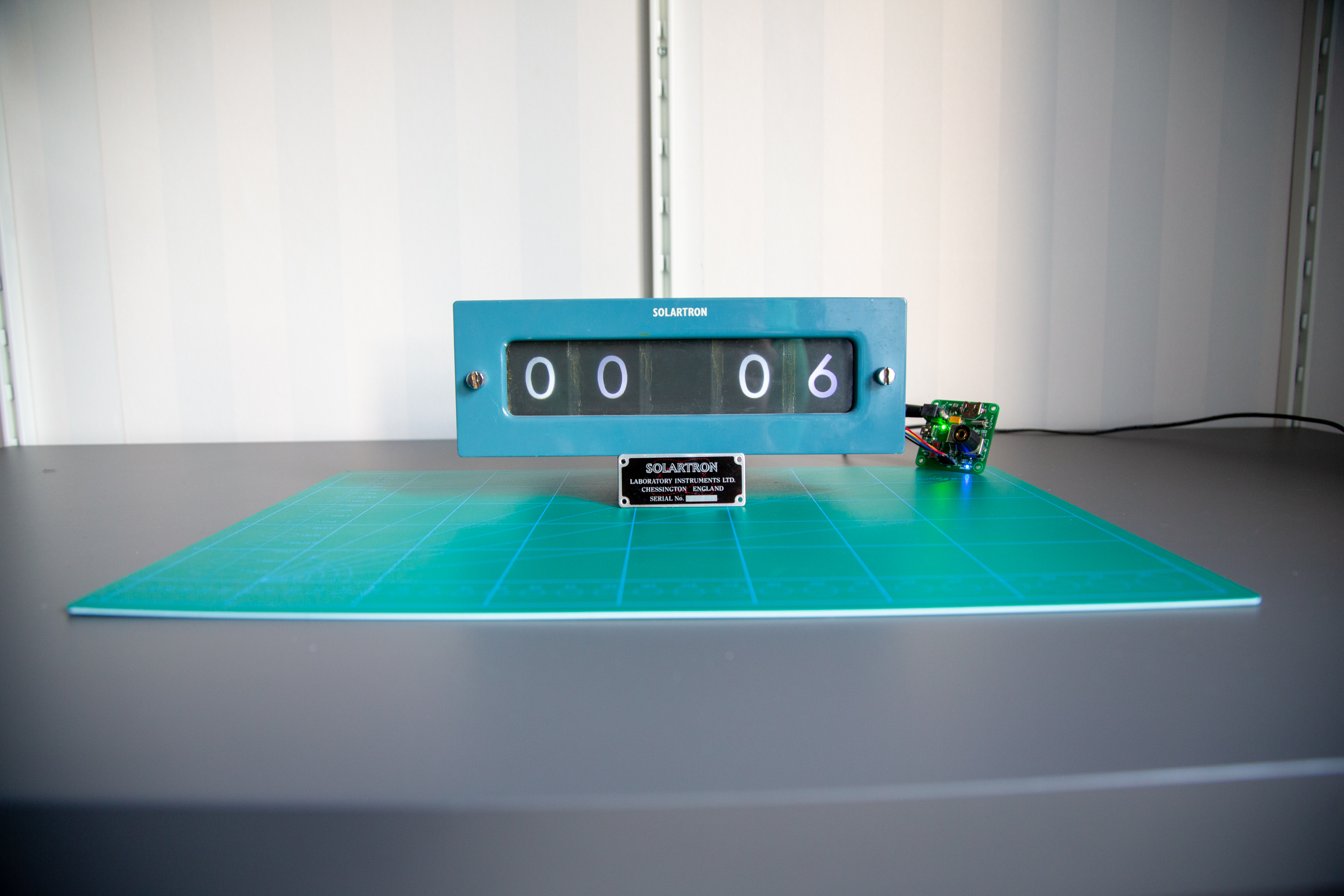
The instrument in question was a Solartron Digital Voltmeter Model LM 1010 21 and I ended up buying it at a local electronics auction. What made the instrument interesting was the back-projecting display, where twelve incandescent bulbs would project one symbol each onto a matte screen.
The instrument isn’t around any more, but the display unit is and it was converted to be using LEDs instead of bulbs. This post documents a bit around the display and the conversion project, a sort of deep-storage archaeology among my old electronics projects. In the end of the post, some reflections on what I would do differently today.
The display
What makes this display intriguing to me, is that size-wise and cost wise this must’ve been quite the investment. I believe nixie-tubes were around at this point (and would probably have made a good candidate), but somehow we ended up with this wonderful thing.
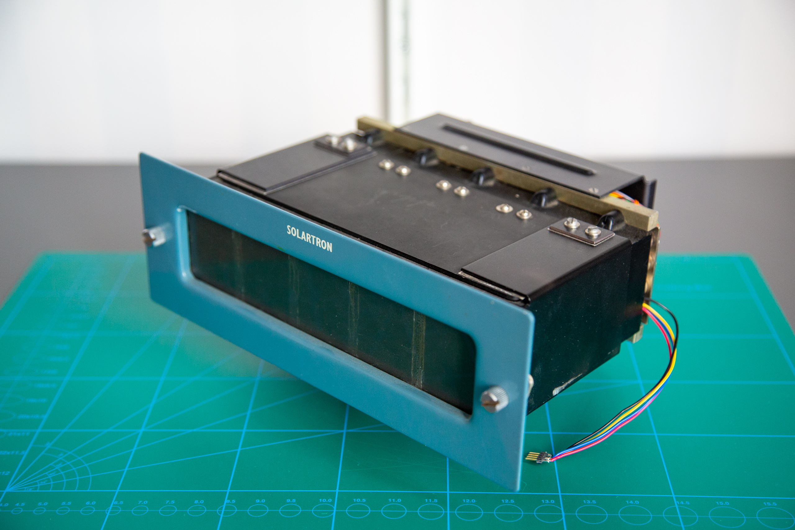
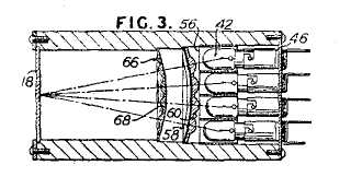
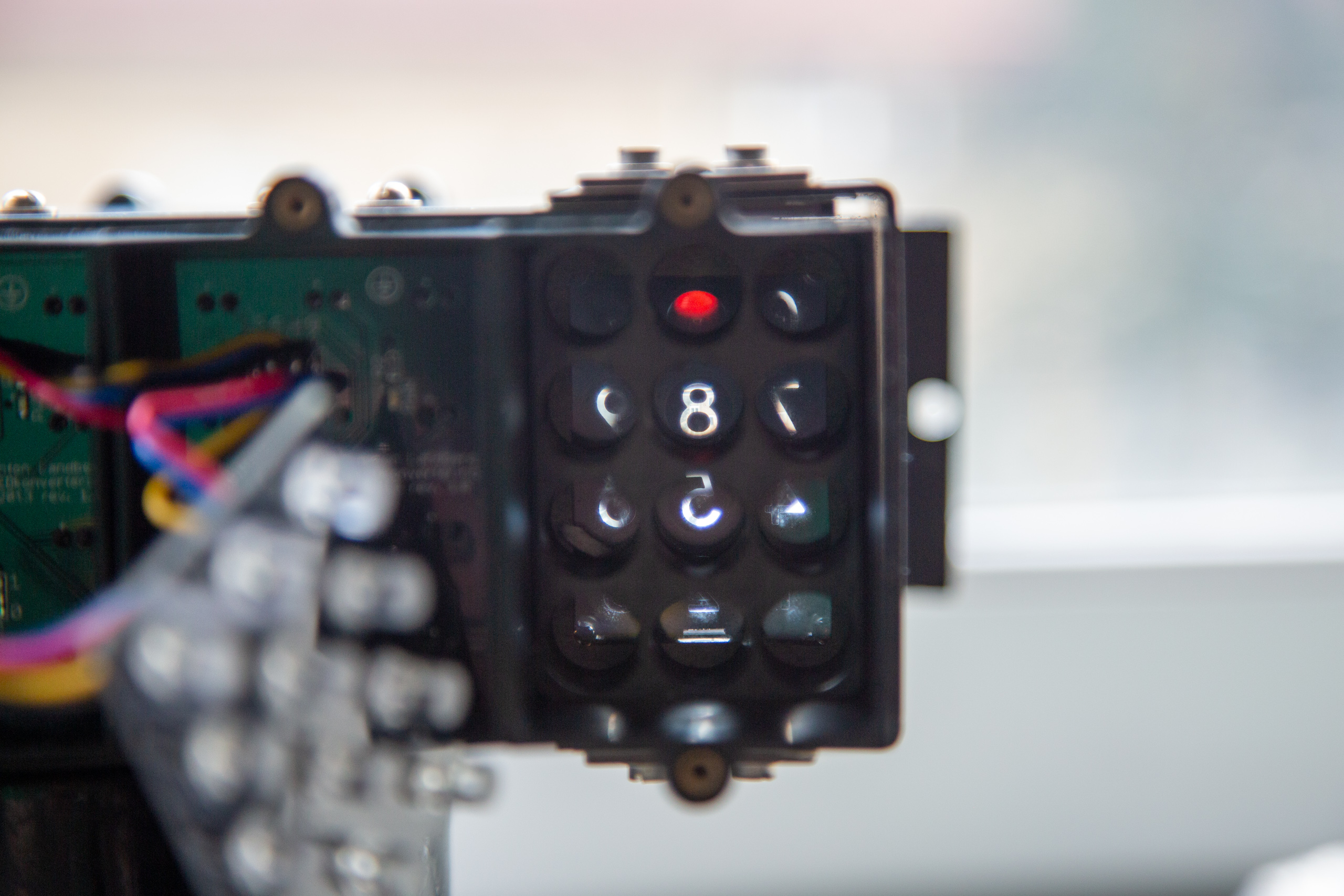
Each display unit contained twelve flashlight bulbs, where each had an optical path of its own. The light would pass through a set of optics, with a symbol cutout2 which would result in a projection on a matte screen in the front of the unit.
Time and place
It’s a bit uncertain why this type of display was chosen for the purpose, as the displays must’ve been relatively expensive to manufacture and are rather big. Timing could be an issue here, nixie tubes started being manufactured mid-fifties and this display unit type would have appeared somewhere around the same time.
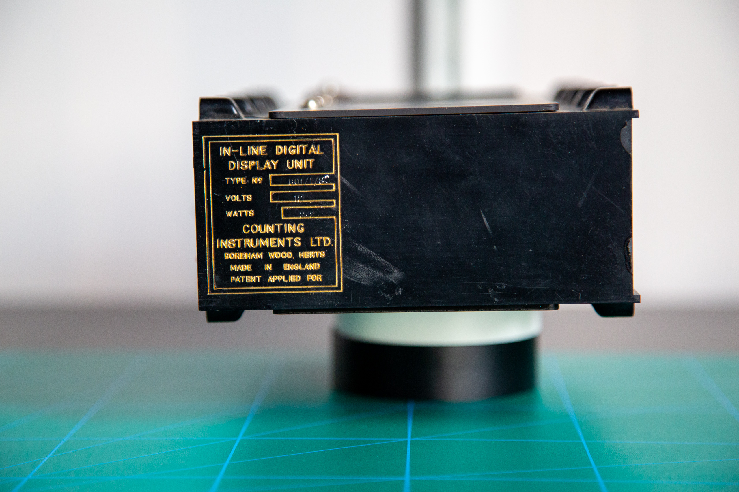
The display unit in question was manufactured in Boreham Wood, Herts, England by Counting Instruments LTD. There is very little documentation I’ve found on the subject. There is a very similar display unit that was manufactured by IEE from 1956, the IEE 10000-1819-B Projection Display. This could be a very early license manufacturing, as the display units in this case list “Patent applied for”, rather than an actual patent reference number as seen in later units. This could put the manufacturing date to be before the patent priority date for the British patent, maybe mid-fifties. That said, this is all speculation.
Lightbulbs and backplane
The display unit has a common ground incoming and each of the bulbs have their end connection wired to a large connector at the back, 60 of them in total. When disassembling the Solartron, it became obvious that it was made so that replacing broken bulbs would be relatively straightforward. That’s further reinforced by the large alignment datums and thumb screws on the front of the faceplate.
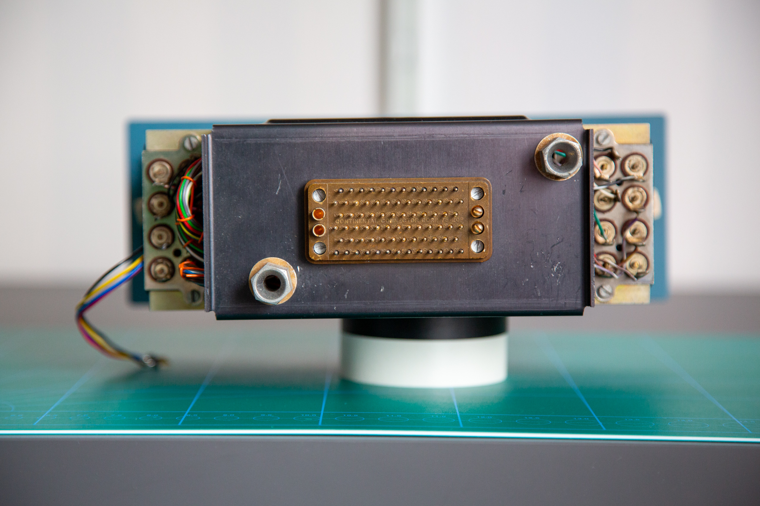
Looking closely at the bulb holders, it can be seen that the outer bulbs are offset slightly further into the optical path. This could be to make the brightness and projection of symbols better.
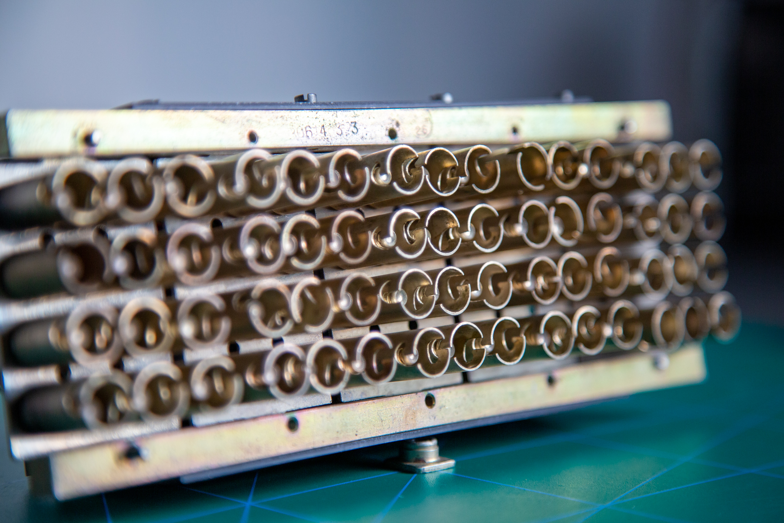
Symbols and optics
Each of the bulbs are warded off so that there is no leakage between symbols and the optics seem to be of relatively good quality, looking carefully one can see the neighboring house though the display. Industrial Alchemy has some good material from the IEE displays that shows how the optics are arranged.
The symbols themselves would be possible to change relatively easy in comparison to nixie tubes, showing different colors would not be an issue either. This is probably one of the reasons this type of display remained in use in addition to Nixie tubes.
The conversion
I had acquired the display unit (and disposed of the rest of the instrument) but it was rather useless without anything to drive or control it. The idea of dealing with bulbs when LEDs were readily available was less than exciting. So, I did what any other electronics student would’ve done - I started a project to convert the display unit to a clock.3
The lifetime of this project would turn out to be pretty long, in part because my firmware skills at the time were lesser and I had for some reason avoided the Arduino platform completely. This also happened as I transitioned from designing boards in Eagle to start using Altium, so the design files are in different states, places and formats.
System solution
Starting the project, a few wishes appeared outside the “I want to do a clock with LEDs”:
- Low amount of cables, so bus interface to control the LEDs
- RTC with battery to keep time
- 8-bit AVR with USB/DFU programming
- Some way to set the time, probably a rotary encoder with button
No hard requirements as such, but none the less it would affect the system solution that emerged.
In short, the hardware would become one board design for the LED replacement repeated for each of the display segments and one board design for the clock controller. The boards would talk to each other over I2C as that would require only four wires in total to be used as communication+power.
LED conversion board
The board that replaces the bulbs is relatively straightforward. The Texas Instruments TLC59116 takes care of current limiting and PWM. The bus wires are just soldered to pads on the board and the I2C address is set by selectively shorting solder jumpers.
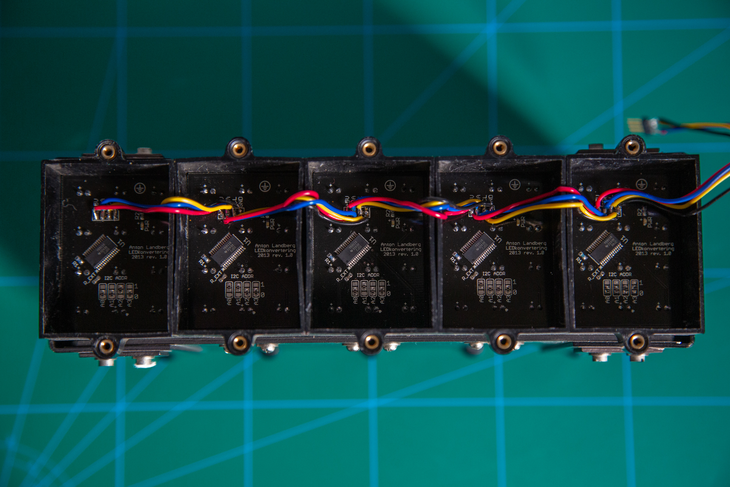
I’d actually argue that figuring out the correct sizing to fit well with the LED apertures is the more difficult part. It turns out that the plastic in the housing doesn’t really have square edges and the fit turned out very tight.
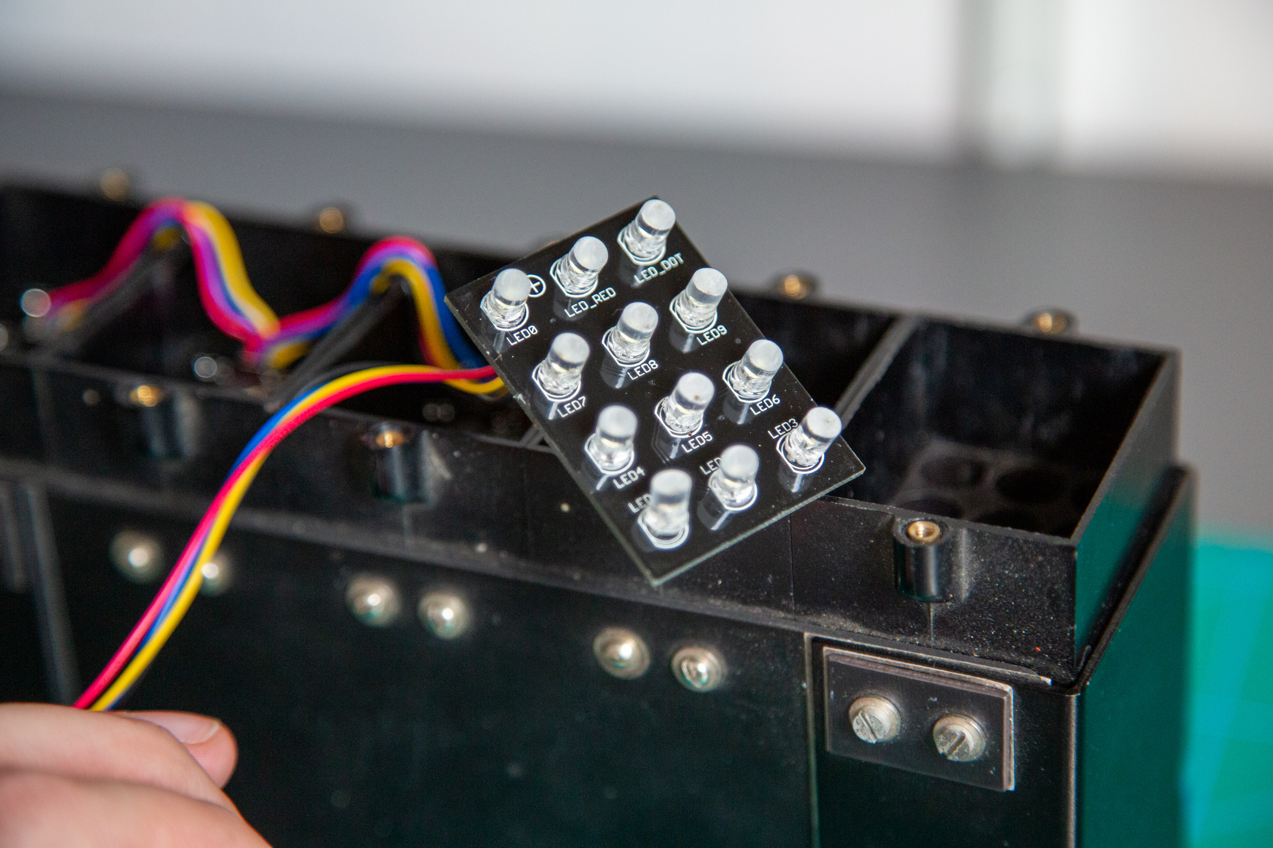
One unexpected issue was that the light spread from the LEDs would be too narrow, so I ground the lens flat to try improve the behavior. This helped somewhat, but it seems that differences in either LED brightness or placement in the apertures result in varying brightness for each symbol anyway. Neither issue is improved by the fact that the brightness from the LEDs are a bit too low for the symbols to be seen well in daylight.
Clock controller board
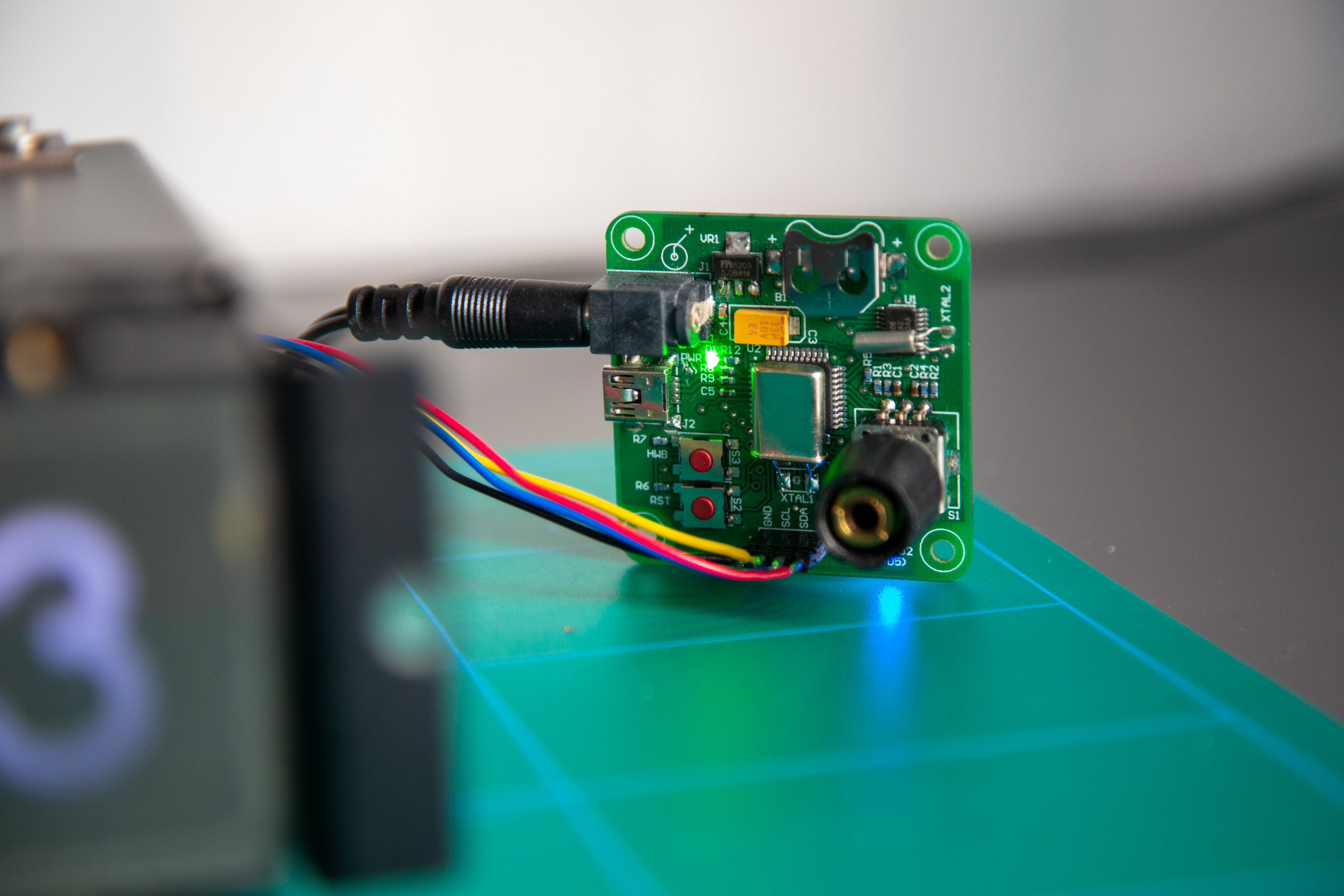
Needless to say, the orchestra will not play without a director. The board, aptly named ClockController, is dated 2015 - two years after the initial LED conversion boards.
Hardware
An ATmega32u4 does the heavy lifting, supported by an external RTC clock with battery and controls the led conversion board over i2c as previously mentioned. Other than that, there’s mostly some buttons and other things for housekeeping needs.4
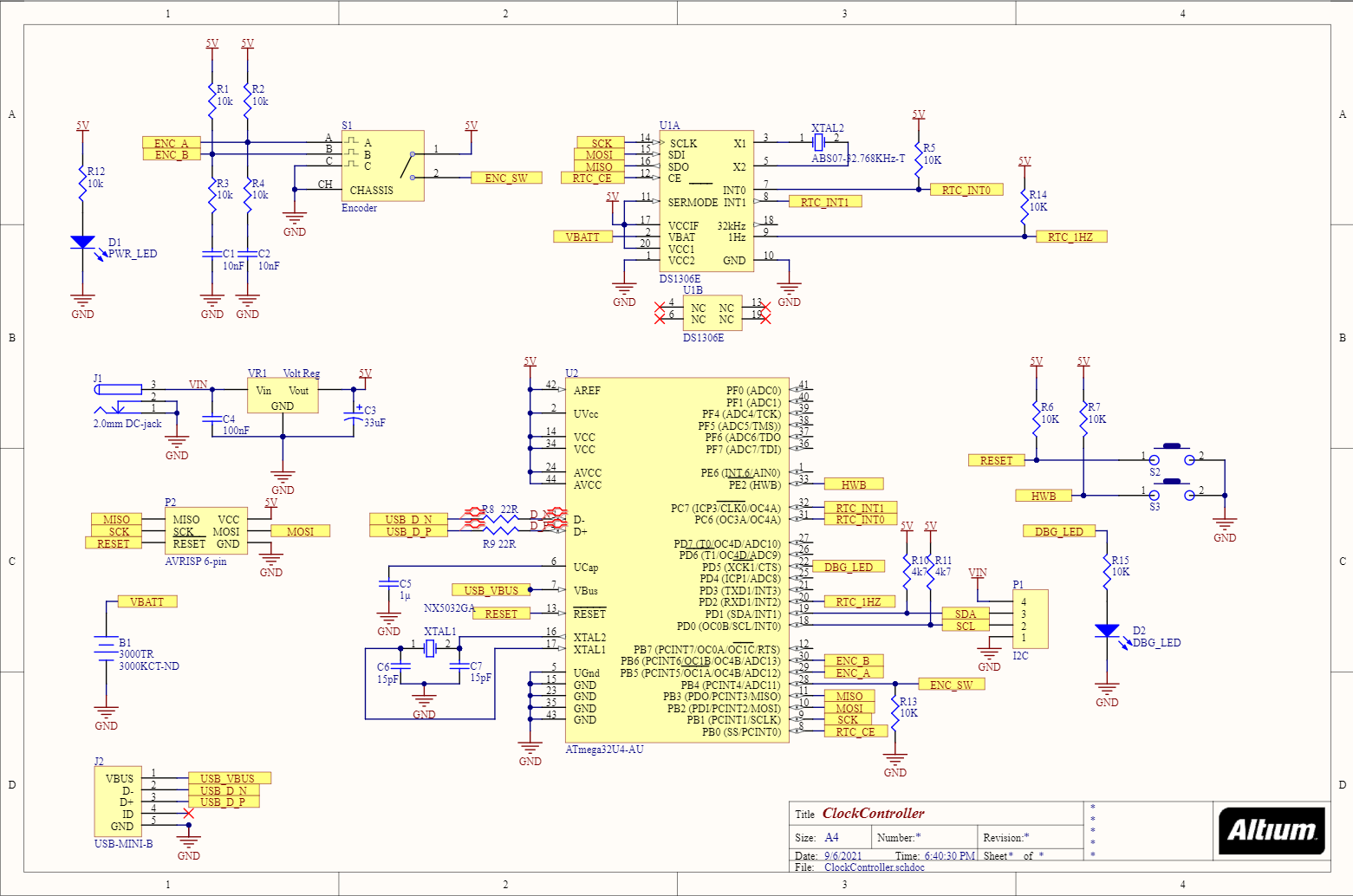
Looking back, especially one thing grabs my attention: The USB connection can only be used for programming via the DFU bootloader. It will actually not even power the MCU, which could’ve been an easy-to-implement quality of life improvement.
Another thing is that I do not remember what I dimensioned this to run at supply-wise. If it’s 5 V, which does work for the full system, there will be a little bit voltage drop over the LDO so that the MCU will be operating at slightly lower than 5 V.
Looking at the LED conversion board side, the TLC59116 does support up to 17 V on the outputs, but I’m pretty sure the LEDs themselves wouldn’t be great fans of that instead as the supply is passed through directly from the ClockController to the LED conversion boards. Not a huge issue, but it’s very possible to operate this things in a way such that it’d destroy itself. The MCU is within it’s recommended operating range at least.
Firmware
After a bit of digging, I think I’ve found at least some variant of firmware that is or has been running on the MCU. Very rudimentary, more or less just verifying that communication with LED boards and RTC is working correctly.
I’ve pasted the main loop below for reference. Other than headers, there are functions implemented for setting numbers for segments, led dimming and similar. A lot of it not very readable, as there are plenty of accesses manipulating the i2c registers directly without any abstraction.
int main(void) {
    initIO();
    i2c_init();
    SPI_init();

    /* Setup the led drivers. */
    for(uint8_t i = 0; i<8; i++) {
        i2c_start(BASE_ADDR + (i<<1) + I2C_WRITE);
        i2c_write(0x80); /* Auto-increment, Select Mode 1 Register. */
        i2c_write(0x80); /* Mode 1 register: Set oscillator on and auto increment. */
        i2c_stop();
    }

    PORTD |= (1<<PD5); /* Set debug led on. */

    while (1) {
        SPI_start();
        SPI_send_recieve(0x01); /* Set Address to read. */
        uint8_t minutes = SPI_send_recieve(0x00); /* Read back result. */
        uint8_t hours = SPI_send_recieve(0x00);
        SPI_stop();


        setLedState(0, (0xF & minutes), LED_ON, 0);
        setLedState(1, (minutes>>4), LED_ON, 0);
        setLedState(3, (0xF & hours), LED_ON, 0);
        setLedState(4, (0x3 & (hours>>4)), LED_ON, 0);
    }
    return 0; // never reached
}
Overall, the code could use a brush-up with amongst other things more readable register abstraction and less busy-wait implementations. There’s plenty of coding to do to actually get something that is ready to use, implementing time setting, interrupts and possibly other things.
Leaving the thing running for a few days, it’s also apparent that there are some bugs in the display code for showing time.
The future?
All in all, I think the project turned out pretty well given what my electronics and firmware skills were at the time. The project did grind to a halt, but most of the groundwork was done to be able to implement at least something.
Now, the thing is that I’d actually like to bring this project to a completion since it’d actually make a pretty nice clock to put in the bookshelf. Doing that, I see two possible paths forward - either completing what is already in place or building something new with a more modern solution.
Fixing what is broken and keeping what’s not is likely to be the quickest solution, maybe a bit of 8-bit AVR nostalgia trip. This would be to ignore the LED brightness issues, but it could also serve as an intermediate step.
Going with something newer, I’d probably base the solution on an ESP32 and a bunch of WS2812B (or compatible) LEDs. That’d result in even fewer wires being needed to route everything together, automatic timekeeping via NTP and the opportunity to get a few more colors out of the display. Power would likely be supplied via USB for the ease of it.
Additionally, there is at the very least some 3D printing to make the thing stand on its own. This would more or less be a frame with supports behind the Solartron front plate, making things way less wobbly. Some small addition to the back of the display unit could also be useful in order to package the electronics, away from dust and prying eyes.
The conclusion
This really is one of those long not-even-running projects that can turn something with an interesting origin and history, into something that can still be useful. I think the industrial design is worthy of a spot in the bookshelf, so why not grant it a place in the spotlight?
How will I proceed? That’s for a different day and another post to deal with.
-
There were a few weird things about that instrument. It looked like the future from the fifties, the serial number plaque was blank and there was a distinct mains hum coming from the enclosure. The instrument itself had probably seen better days. ↩
-
In this case, the symbols would be the digits 0-9, a decimal dot and a red background. The red background was probably used to signal out-of-range or similar. ↩
-
Eh, well, what any nerdy electronics student with an actual drive to build things would’ve. That doesn’t mean things get finished. The keyword here is started… ↩
-
The keen eye will notice the two crystal bodge jobs, that was (if I recall correctly) due to the actual smd crystals being unobtanium. ↩